Select
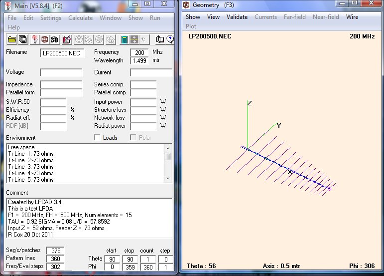
"Calculate" from the 4NEC2 menu bar, then select "NEC Output Data".
You should see something similar to the screenshot below.
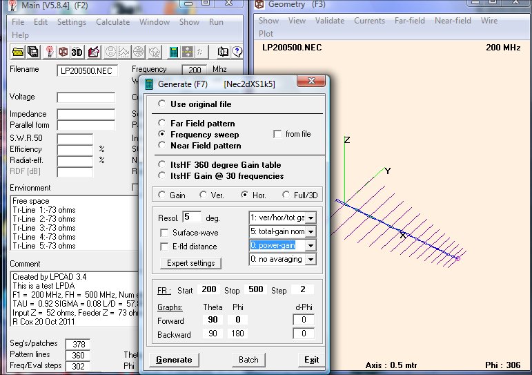
Select "Frequency Sweep", "Hor.", "0:Power Gain", Start 200,
Stop
500, Step 2, Theta Forward 90, Theta Backward -90, then press
"Generate".
After
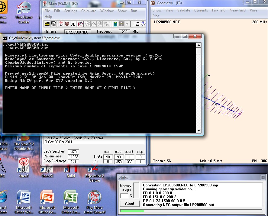
you press "Generate", 4NEC2 opens the input file and begins the
calculations. Your screen should look similar to the one
below
until done.
After the calculations are
done, you should see this display:
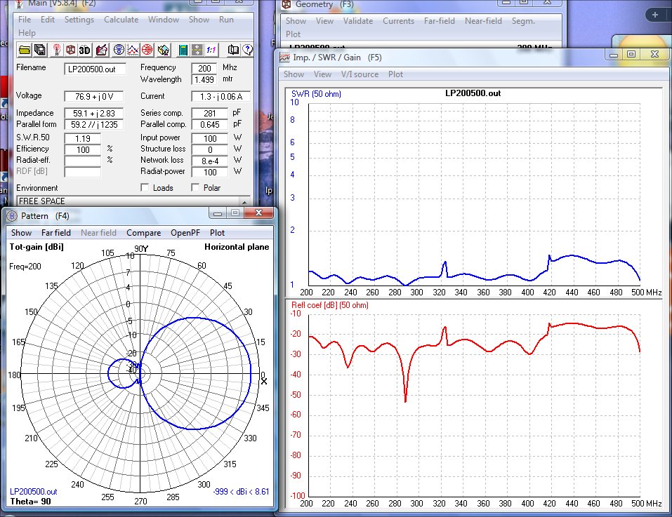
In
the VSWR sweep, you can see 2 very sharp "spikes", one near 320 MHz and
another near 420 MHz. These are anomolous resonances that
come
from the impedance of the rear short transformed through 1/2 wavelength
of the feeder to the approximate location of the active elements at
these frequencies.
Below, you can view the Gain and F/B sweeps of this antenna.
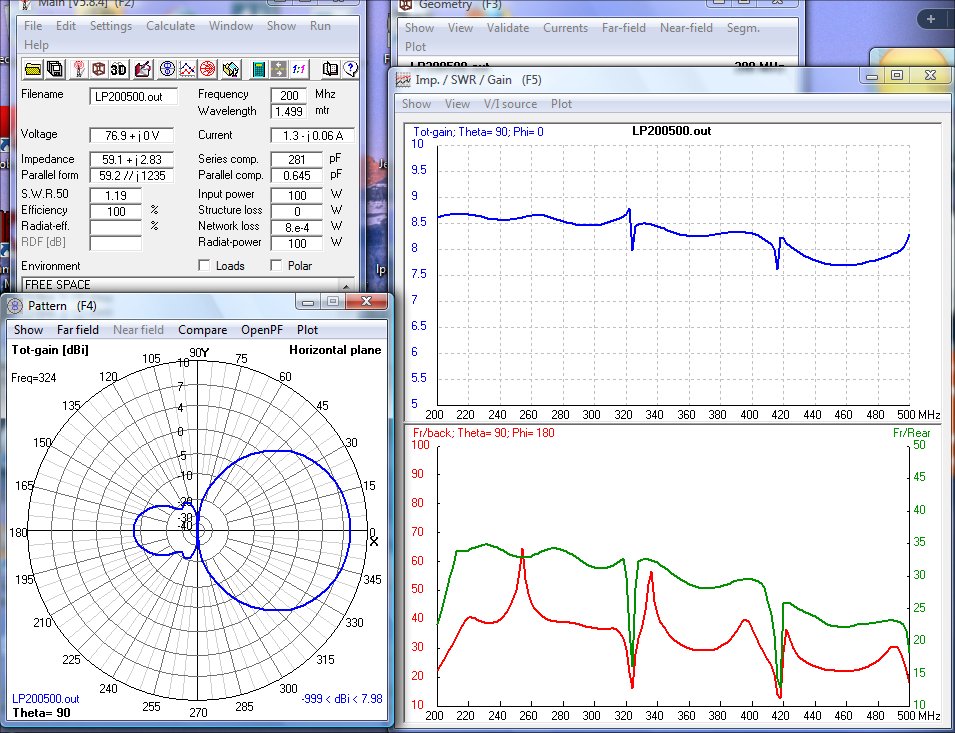
You
can notice that these "spikes" also occur in the gain and F/B at
roughly the same frequencies. The pattern shown on the left
shows
the increased backlobe at 324 MHz, near one of the "spikes".
For
most Ham uses, these "spikes" can be moved to frequencies where they
don't cause any problems. To move the spikes, move the
location
of the rear termination - closer to the rear element moves the "spikes"
higher in frequency - farther away from the rear element moves them
lower. If your application requires no "spikes" or very
minimal
change in gain & F/B, then you should redesign the LP by using
a
Tau of 0.93 or higher.
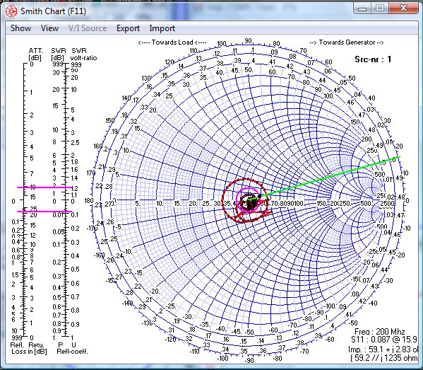
Here is the Smith Chart display for this antenna. Notice that the
impedance nicely circles around 50 ohms!


