
(16 March 2016)
Log Periodic Dipole Array Design
In 1957, R.H. DuHamel and D.E. Isbell of the University of Illinois published the first work on what was to become known as the log periodic dipole array. These remarkable antennas exhibit relatively uniform input impedances, VSWR, and radiation characteristics over an extremely wide range of frequencies. In essence, log periodic arrays are a group of parallel dipole elements of increasing length strung together and fed alternately through a common balanced transmission line.
The log periodic antenna works the way one intuitively would expect. Its “active region,” -- that portion of the antenna which is radiating or receiving radiation most efficiently -- shifts with frequency. The longest element is active at the antenna’s lowest usable frequency where it acts as a half wave dipole. As the frequency shifts upward, the active region shifts forward. The upper frequency limit of the antenna is a function of the shortest elements.
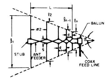
Figure 1
The basic LPDA geometry is that shown in the above Figure 1. Each element is shorter than the element to its left. Ratio of each dipole element to each adjacent element is constant, and is referred to as Tau (t). The other critical dimension is the ratio of the spacing between adjacent elements to the longer element length, designated Sigma (s). Sigma is sometimes called the relative spacing constant. These 2 constants, along with the minimum and maximum frequencies are enough to describe most log-periodic dipole arrays. Another relatively important constant is the L/d ratio (length to diameter of each element).
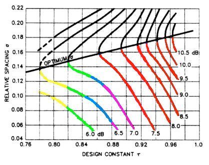
F/B: Yellow = 8-11 dB
Green = 12-14 dB Blue = 15-19 dB Pink =
20-24 dB Red
= 25 dB+
Figure 2
The curves shown in Figure 2 have been used for many years to estimate the gain of LPDA designs, based upon the constants Tau and Sigma. These should be used with caution, as they are only an approximation of performance, based on one particular L/d and an octave bandwidth. Generally, higher values of Tau also give higher F/B (front to back ratios) and higher values of Sigma generally give higher gain. Rarely are LPDA's designed using values above the optimum Sigma line as these would be extremely large. For compact LPDA's, I like to use Tau in the range of 0.84 to 0.90 and Sigma between 0.04 and 0.06. This produces gain between 6.0 and 6.5 dBi with F/B between 15 and 20 dB. For F/B greater than 25 dB, Tau generally needs to be greater than 0.92.
I have always wanted to see how close Figure 2 is to what the NEC models give. Here is my attempt. Stay tuned - it may take a while.
Median GAIN
| Tau>> SIGMA V V |
0.80 | 0.81 | 0.82 | 0.83 | 0.84 | 0.85 | 0.86 | 0.87 | 0.88 | 0.89 | 0.90 | 0.91 | 0.92 | 0.93 | 0.94 | 0.95 | 0.96 | 0.97 | 0.98 | 0.99 |
| 0.18 | ||||||||||||||||||||
| 0.17 | ||||||||||||||||||||
| 0.16 | ||||||||||||||||||||
| 0.15 | ||||||||||||||||||||
| 0.14 | ||||||||||||||||||||
| 0.13 | ||||||||||||||||||||
| 0.12 | 7.1 | 7.4 | 7.4 | 7.8 | 7.9 | 8.3 | 8.7 | 8.8 | 8.9 | 9.4 | 9.8 | 10.2 | 10.7 | 11.2 | ||||||
| 0.11 | 6.5 | 8.4 | 8.6 | 9.1 | 9.5 | 10.0 | 10.3 | 10.8 | 12.0 | |||||||||||
| 0.10 | 6.6 | 7.2 | 7.4 | 7.6 | 7.6 | 8.0 | 8.3 | 8.3 | 8.5 | 9.0 | 9.3 | 9.7 | 10.1 | 11.0 | 11.6 | |||||
| 0.09 | 6.6 | 7.1 | 7.2 | 7.4 | 7.3 | 7.6 | 8.0 | 8.2 | 8.5 | 8.7 | 9.1 | 9.5 | 9.8 | 10.7 | 11.4 | |||||
| 0.08 | 6.5 | 7.0 | 7.1 | 7.3 | 7.5 | 7.7 | 7.8 | 8.0 | 8.2 | 8.5 | 8.8 | 9.0 | 9.9 | 10.6 | 10.9 | |||||
| 0.07 | 6.1 | 6.5 | 6.8 | 7.0 | 6.9 | 7.3 | 7.6 | 7.8 | 8.0 | 8.2 | 8.4 | 8.9 | 9.2 | 10.0 | 10.7 | |||||
| 0.06 | 6.1 | 6.3 | 6.5 | 6.8 | 6.8 | 7.1 | 7.3 | 7.5 | 7.7 | 8.0 | 8.2 | 8.6 | 8.9 | 9.6 | 10.4 | |||||
| 0.05 | 5.8 | 5.9 | 6.1 | 6.3 | 6.6 | 6.75 | 6.9 | 7.1 | 7.3 | 7.5 | 7.8 | 8.3 | 8.6 | 9.1 | 9.9 | |||||
| 0.04 | 5.5 | 5.6 | 5.65 | 5.7 | 5.75 | 5.9 | 6.0 | 6.25 | 6.3 | 6.5 | 6.55 | 6.75 | 7.0 | 7.1 | 7.5 | 7.9 | 8.3 | 8.7 | 9.5 |
LPDA median Gain (dBi) based on 250-500 MHz (octave) design with L/D = 50 (largest dia = 0.46") and no rear short
| Tau>> SIGMA V V |
0.80 | 0.81 | 0.82 | 0.83 | 0.84 | 0.85 | 0.86 | 0.87 | 0.88 | 0.89 | 0.90 | 0.91 | 0.92 | 0.93 | 0.94 | 0.95 | 0.96 | 0.97 | 0.98 | 0.99 |
| 0.18 | ||||||||||||||||||||
| 0.17 | ||||||||||||||||||||
| 0.16 | ||||||||||||||||||||
| 0.15 | ||||||||||||||||||||
| 0.14 | ||||||||||||||||||||
| 0.13 | ||||||||||||||||||||
| 0.12 | 21 | 24 | 24 | 27 | 26 | 28 | 33 | 32 | 33 | 36 | 37 | 39 | 36 | 38 | ||||||
| 0.11 | 19 | 25 | 25 | 25 | 26 | 29 | 30 | 30 | 32 | |||||||||||
| 0.10 | 20 | 22 | 19 | 21 | 23 | 25 | 25 | 26 | 25 | 25 | 27 | 28 | 30 | 30 | 31 | |||||
| 0.09 | 19 | 20 | 21 | 22 | 22 | 24 | 23 | 25 | 26 | 26 | 26 | 27 | 29 | 30 | 30 | |||||
| 0.08 | 15 | 17 | 18 | 20 | 21 | 22 | 24 | 27 | 28 | 30 | 30 | 30 | 30+ | 30+ | 36 | |||||
| 0.07 | 15 | 16 | 19 | 19 | 21 | 22 | 23 | 24 | 26 | 30 | 30 | 30 | 30+ | 30+ | 33 | |||||
| 0.06 | 15 | 16 | 17 | 18 | 20 | 20 | 21 | 22 | 23 | 25 | 27 | 32 | 32 | 32 | 34 | |||||
| 0.05 | 12 | 13 | 14 | 16 | 18 | 19 | 20 | 21 | 23 | 25 | 27 | 34 | 30 | 31 | 31 | |||||
| 0.04 | 9 | 10.5 | 11 | 11 | 12 | 13 | 14 | 14 | 15 | 16 | 17 | 18 | 20 | 21 | 22 | 25 | 27 | 30 | 31 |
LPDA median F/B (dB) based on 250-500 MHz (octave) design with L/D = 50 (largest dia = 0.46") and no rear short
Comments are welcome!
contact Roger: email to
rgcox2 (at) gmail.com
Roger Cox W8IO - Spring Lake, MI